team8s
brandon, eric, henri, sophie
Final Design
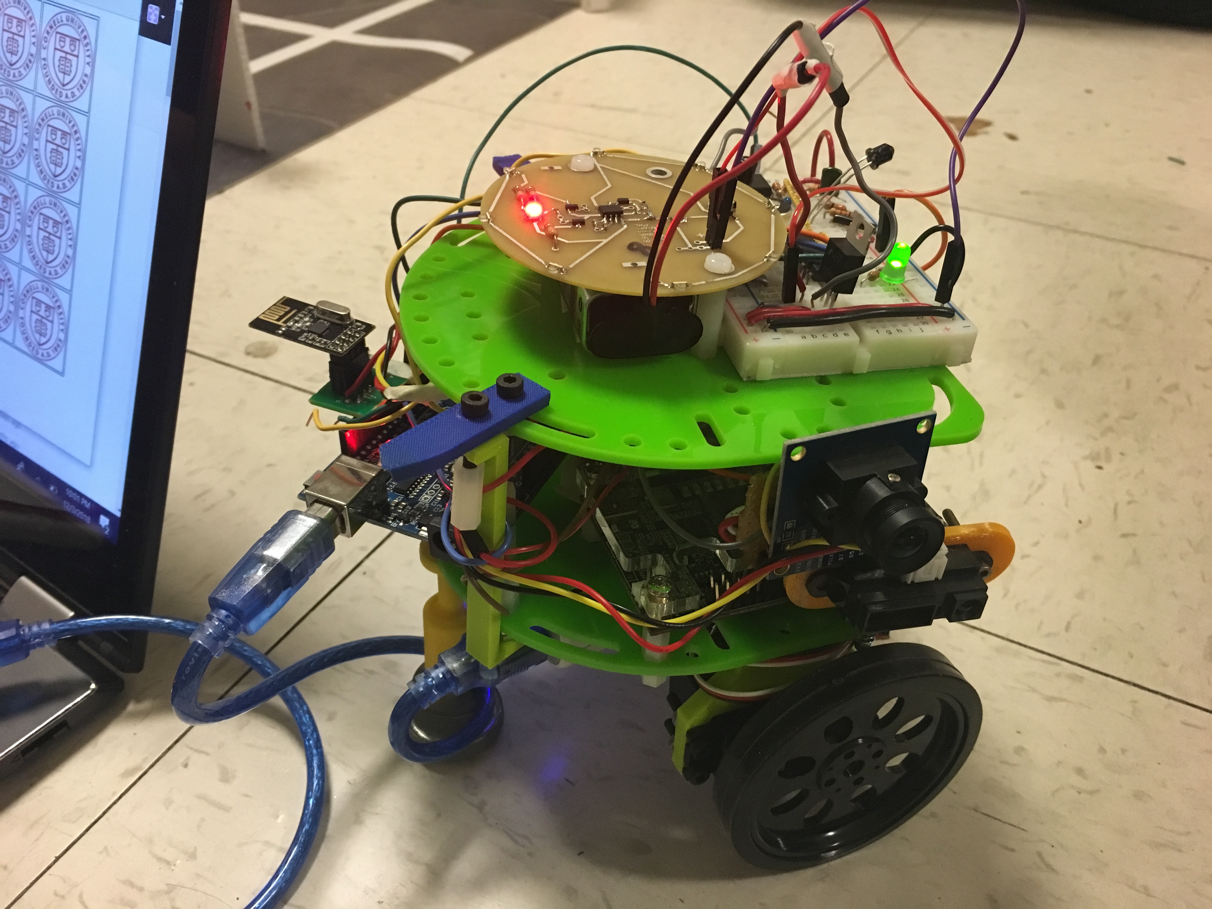
Our Final Robot
Introduction
Our robot son -- a young, misunderstood collection of spark and drive -- has gone through a lot of growth since the beginning of the semester. Over the last several weeks, team8s has spent many hours in lab integrating all of the individual subsystems with the limited time that we had -- creating a base station, a navigation algorithm, and treasure detection system. Although many things worked individually, we had to debug a lot upon combining them. Not everything turned out perfect, partially because of how pressed we were for time, but our (kind of) intelligent physical system has come a long way from just flashing an LED on an Arduino.
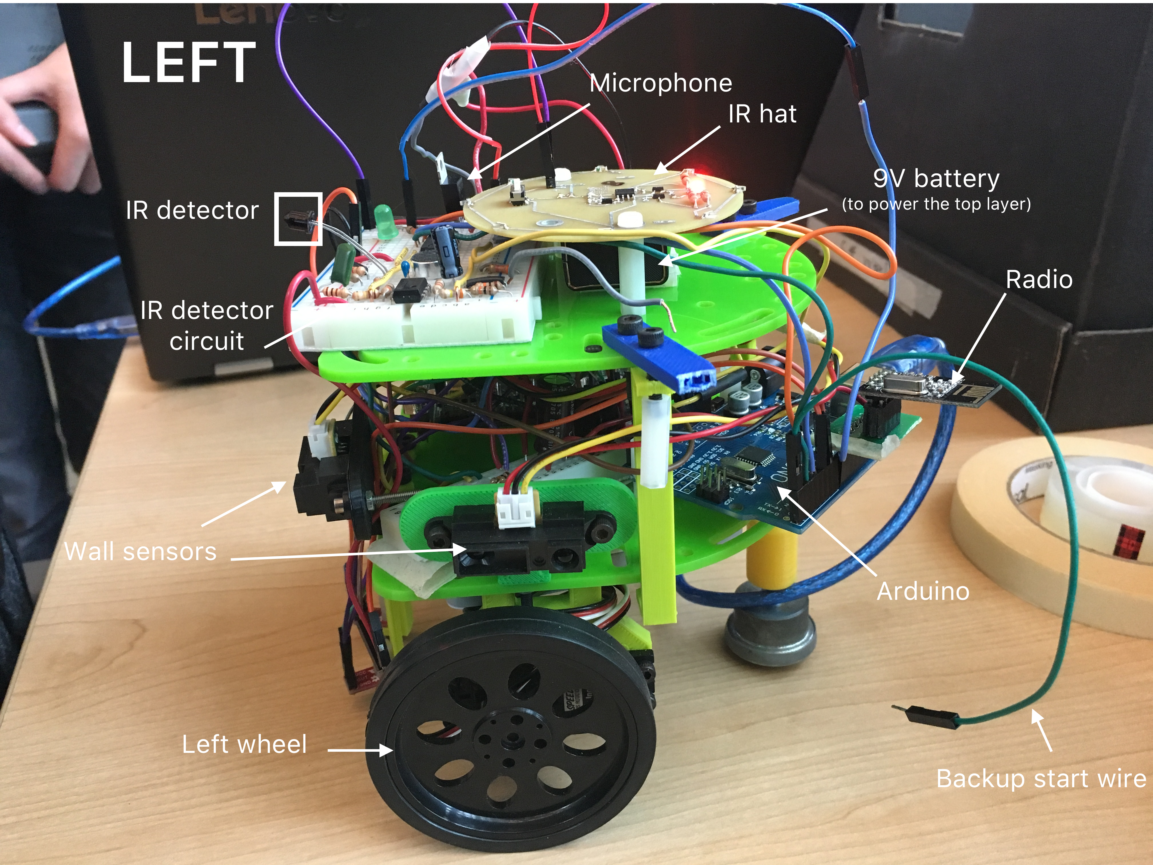
Mechanical Overview
- Arduino
- FPGA
- IR hat/detector
- Camera
- Microphone
- Servos
- Wall sensors
- Line sensors
- Wheels
- Radio
- 9V battery
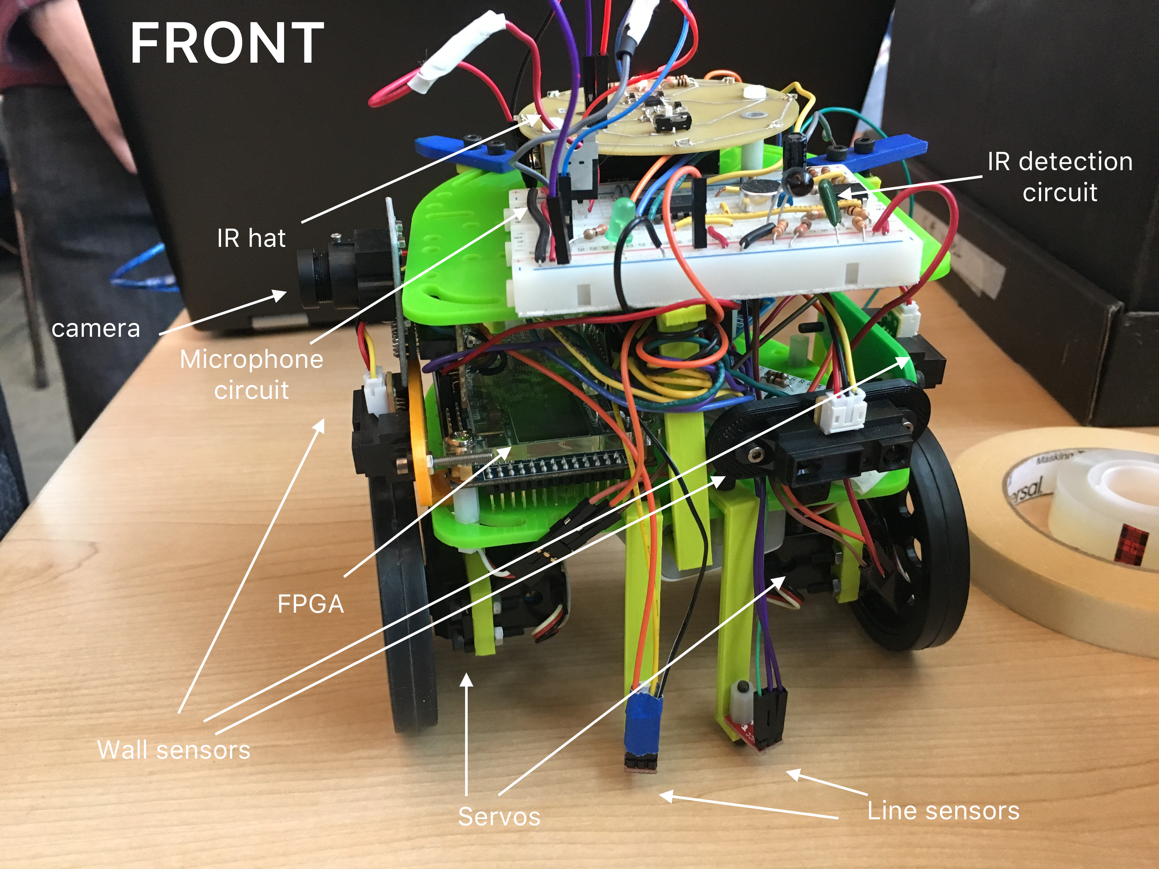
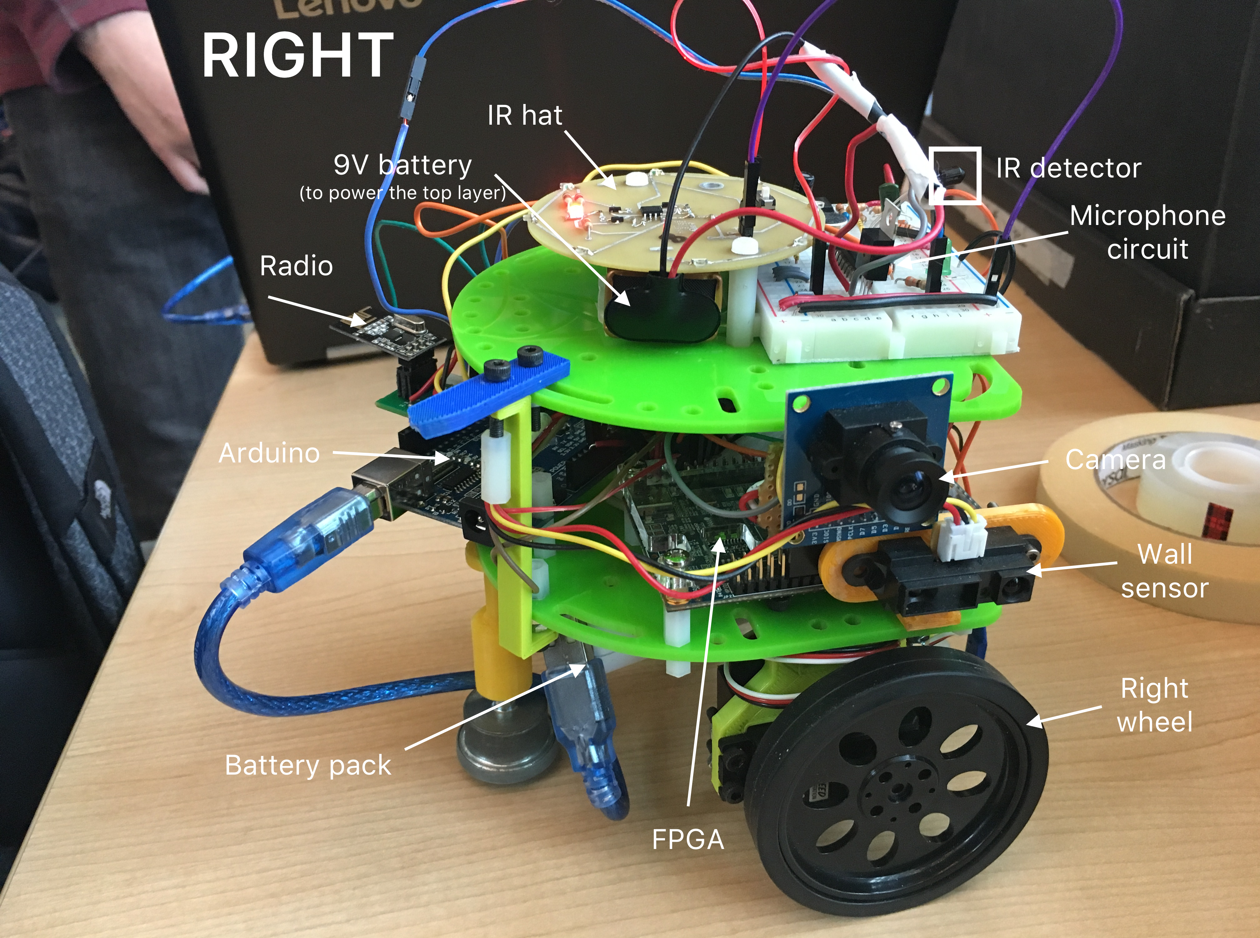
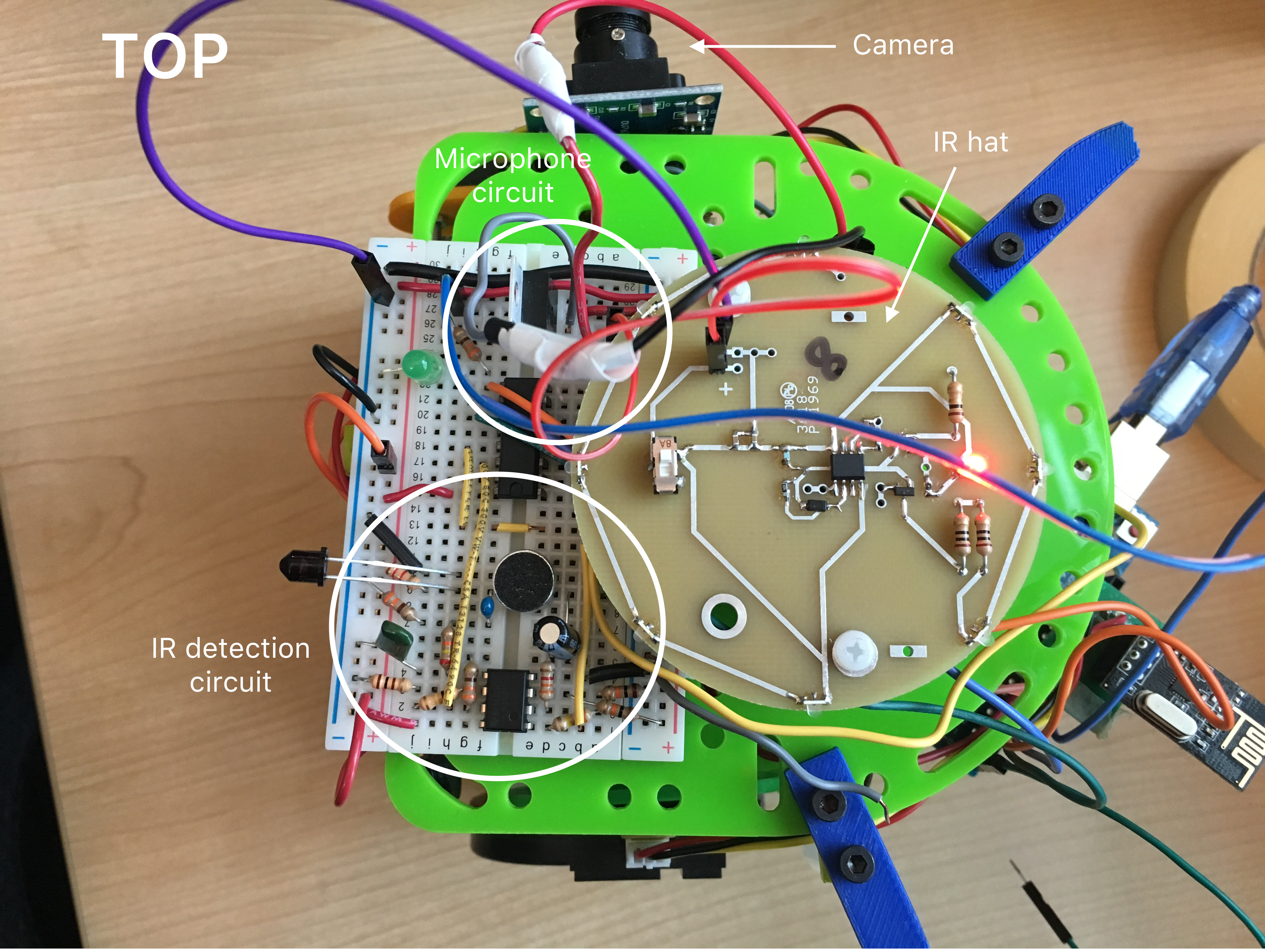
Although we didn’t make use of protoboards, a 3D printer or the PCB milling machine as hoped (and primarily just used lab components), we did make a custom camera mount to avoid poor-fitting, wires and keep our FPGA neater.
Starting the Maze
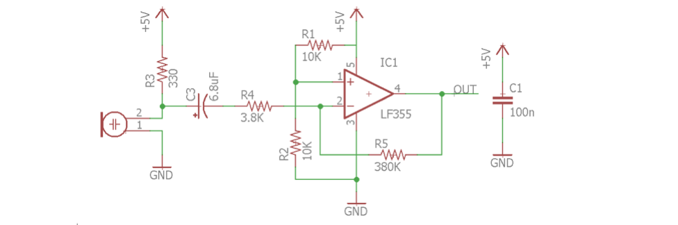
Microphone
Our robot needed to start the maze at a 600 Hz tone. In order to do this, we assembled a microphone circuit that would detect the tone and check if it it was (around) 600 Hz or not. The circuit consisted of a microphone whose output went into a filter and amplifier:
Using the FFT library (more about this in our lab 2 documentation), we determined that a 660Hz tone would appear in the 3rd bin; thus, when that bin surpassed a certain level, we knew that the correct tone had played and the robot could start.
We realized during the competition that our chosen threshold was a little off, since our robot kept starting at some voices -- particularly Brandon’s, although he may have just been claiming a favorite parent. For future accuracy, we would raise the threshold and test in a space with a lot more noise.
Failsafe:
Just in case this didn’t work, however, we decided to have a backup mechanism to start our robot. Instead of having a pushbutton, we had two open wires; one was connected to a pin on the Arduino, and one was attached to ground. If they touched -- ie. if the pin went LOW -- the robot would start. Thus, in order to bypass the microphone circuit and jump straight into movement, we simply had to touch the two wires.
This is something that came in very handy while testing our robot without repeatedly playing the 600 Hz tone annoyingly, and a starting mechanism we ended up using in the final competition when our robot went off course and we had to reset it!
At the end, the conditions leading to our robot starting -- considering both the microphone and the failsafe -- were as follows:
            if ((fft_log_out[3] > 150) || startButton == 0)
              start = 1;
Basic Navigation and Sensors
Our robot is capable of line-following, sensing walls, and turning!
Movement and Line-following
It’s been a long time since our son’s first steps -- rolls? -- but the movement we established since lab 1 has held steady throughout the weeks.
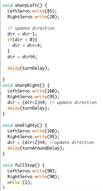
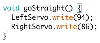
In order to move, we could set the analog output of the servo pins to either 0, 90, or 180 to move forward, stop, or move backwards. (Due to lack of symmetry, however, setting one servo’s 0 would be forward, while the other’s 0 would be backwards.) To turn, we turned one servo forwards and the other backwards and delayed.
We used IR sensors in order to follow a line: one on each side of the line, which turned out to be an efficient configuration: if the robot drifted a little to the left, the right sensor would sense the white line, the robot turns a little bit to the right to offset the drift by briefly speeding up its left servo, and vice versa. Using the serial monitor, we determined that something “white” corresponded to a value of 850, while black was 650.
General code:
          void followLine() {
            bool rightIsWhite = analogRead(SENSERIGHT) < 860;
            bool leftIsWhite = analogRead(SENSELEFT) < 860;
            bool reachedIntersection = rightIsWhite && leftIsWhite;
            if (reachedIntersection) {
              LeftServo.write(90);
              RightServo.write(90);
            }
            else if (rightIsWhite) {
              turnRight();
            }
            else if (leftIsWhite) {
              turnLeft();
            }
            else {
              goStraight();
            }
          }
This video depicts our robot line-following:
Wall Detection
We have three wall sensors located on the front, left and right sides of the robot. Each of these wall sensors are connected to an analog input pin on the Arduino. By remembering the starting orientation of the robot and what turns have been performed since then, we are able to determine from these 3 sensors whether there are walls on the north,east, south or west side of the location that the robot is at.
In order to ensure proper detection, a short test script was written to continuously read each of the wall sensor values and print the respective value to the serial monitor. Then, by checking the serial monitor and placing a wall in front of each sensor, we are able to check what an appropriate threshold value for each wall sensor should be.
In this example, when there is no wall to the right, the robot turns to the right. And when there is both a right and front wall, the robot turns around. On right turns, the green LED is high, and when the robot is going straight, the red LED is high. We were later able to build upon wall-following in order to implement a better traversal algorithm.
IR Detection
We built a bandpass filter to be able to detect other robots emitting a frequency of 6.08kHz. The purpose of the filter is to cut out other frequencies, like the IR decoys. To get the resistor and capacitor values for our circuit we used an online calculator.
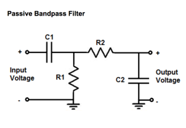
Component values
C1 = 100nF
R1 = 330 Ohms (to ground)
C2 = 1nF
R2 = 24 kOhms (to output)
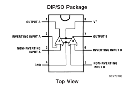
We also built an amplifier because the reading we got from the output of the transistor was very small in magnitude, especially from far away. We chose to use an non-inverting op amp circuit because it is simple and easy to build. We based our design on the image below. The gain of the non-inverting amp is equal to 1 + Rf/R2, so with the resistor values we chose, we have a theoretical gain of about 1000. The pinout for the op amp that we used is also below.
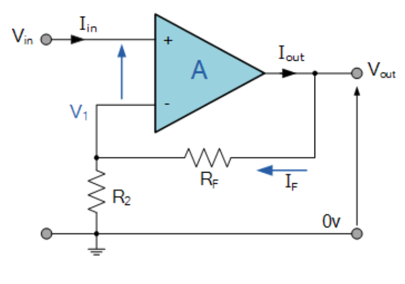
Resistor values
Rf = 100 kOhms
R2 = 100 Ohms
Texas Instruments LM358P
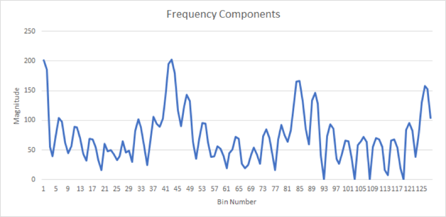
There are several peaks, which are harmonics of the actual signal. The highest peak occurs in bin number 43, where the magnitude is about 200 when the transistor and hat are very close to each other. Now to check if we are near an IR hat, we just run the code from the example sketch, and instead of printing all of the values recorded at the end we just check the value in bin 43 (index 42).
If the magnitude is above a certain threshold, we printed “IR Detected” to the serial monitor; if it is below that threshold, we print “IR Not Detected”.
When we actually implemented the code in our robot, we changed the code to stopping at the intersection until the other robot is no longer detected. In addition, while integrating the IR sensor and the microphone sensor to the robot, we found that the 5V from the arduino was not enough to power the 2 amplifier circuits. Due to this, we used a 9V to 5V linear regulator to supply power to the op amp circuits.
Traversal Algorithm
Our robot traverses the maze by finding the nearest unexplored location in the maze using Djikstra’s algorithm. The distance to the nearest location is calculated using the Manhattan distance with an additional cost for if the robot must turn to reach this location. This gives our robot priority to unexplored locations that allow it to continue moving in a straight line. This arbitration for determining the next location can be seen in the snippet below:
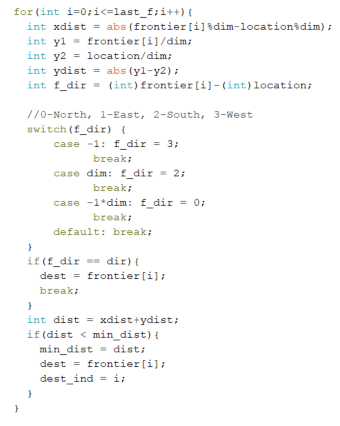
Once a destination is selected using this algorithm, it looks at the locations immediately surrounding it and checks to see if any of them match the destination. Otherwise, it goes back to the previous location to see if any of those surrounding squares match the destination and so on until it reaches the destination.
While this is not the most efficient algorithm to find a path to the unexplored node, it can be implemented by simply using a stack to keep track of the current path. This is a far smaller amount of memory than is required to perform a breadth first search (BFS) to find the shortest path to the unexplored node. (When using BFS, the recursive calls used to calculate the path from each node filled up the call stack and the Arduino memory after traversing around 20 squares.)
This algorithm allows our robot to theoretically reach every node in the maze.
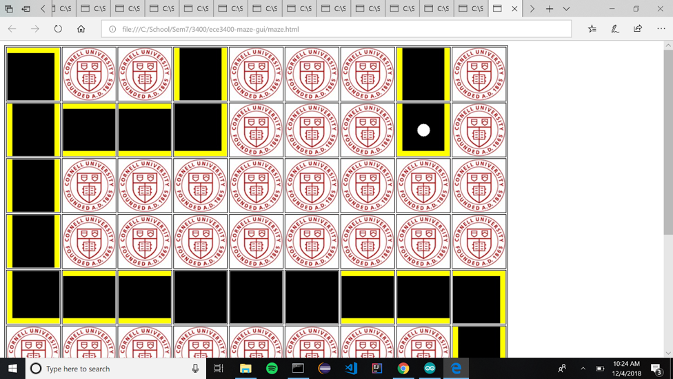
When our MATLAB code was converted to Arduino code and integrated it onto the robot, we realized that the data structures used and the recursive function calls were too much for the robot to handle. This is what led to the change in design from a BFS path planning algortihm to a retrace your steps algorithm. This image is from the night before the competition:
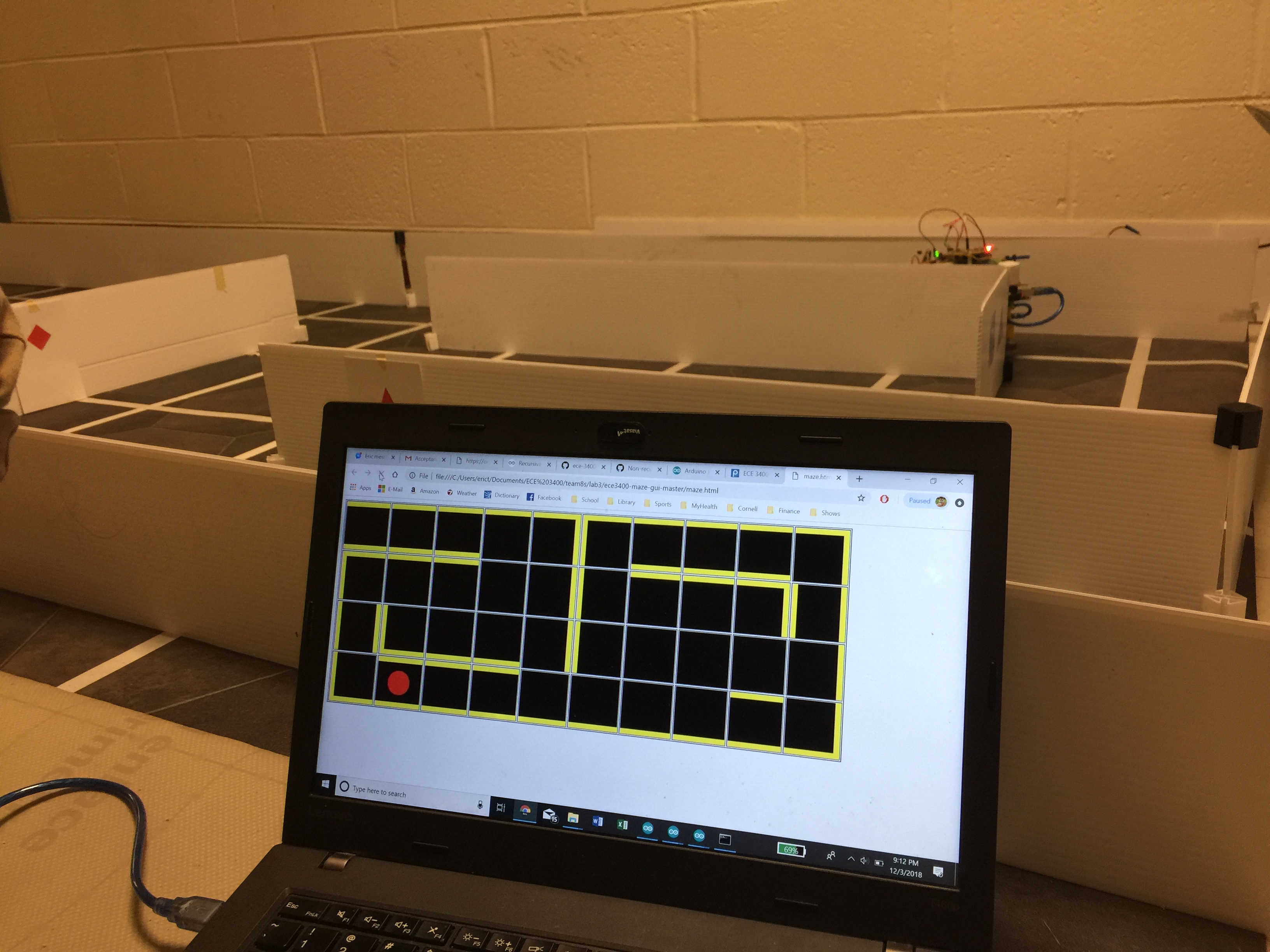
(Note: The one false wall is from a person walking through and getting in the way of our robot. We couldn’t get a cleaner reading because there were so. many. people. in and walking through the maze that night.)
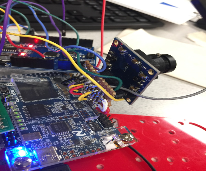
Camera and Treasures
Our robot is capable of detecting variations in color indicating either red or blue treasures through an FPGA-controlled camera.
Color Detection
In order to tell if a shape our camera was looking at was red or blue, we continually checked the current pixel’s value on each posedge of the clock. If this was predominantly red, we would iterate RED_PIXELS; if it was predominantly blue, we would add to BLUE_PIXELS.
We also iterated a value “pixel_count” to determine if we were at the end of reading an entire frame.
Once we had finished reading an entire frame, we then checked if we had found significantly more red pixels than blue pixels; if so, then we iterated the variable RED_FRAMES; if there was significantly more blue than red, we iterated BLUE_FRAMES; and if the difference between red and blue pixels was relatively negligible, we iterated NONE_FRAMES. We then reset RED_PIXELS, BLUE_PIXELS, and pixel_count.
In order to prevent frame overflow, we ensured that if any of RED_FRAMES, BLUE_FRAMES, or NONE_FRAMES hit capacity (== 10’b1111111111), we decremented all the frames’ values by 1 (provided they were greater than zero).
We then chose output our result as follows:

That is, in bit 0 we would return a 0 if there were more blue frames and a 1 if there were more red frames; in bit 1, we would return a 1 if there were more “none” frames than either blue or red, and a 0 otherwise.
Due to the lack of time, we did not integrate the camera into the final design of the robot even though the FPGA and camera were mounted and individually functional -- other parts of the robot, like properly traversing the maze, took more precedent funtionality- and point-wise. Given more time, we would have spent more time effort making shape detection work and developing GUI integration; in addition, we would have had to figure out how to spin the robot in order to check for treasures on all sides of the walls, or developed an algorithm to check all of the walls after a successful completed maze traversal by re-exploring all walls and keeping them to the robot’s right (where the camera was mounted)
Radio Communications & GUI
To start, we used the “Getting Started” example code from here to transmit and receive messages between the two radios.
We downloaded the GUI provided by the TAs from here.
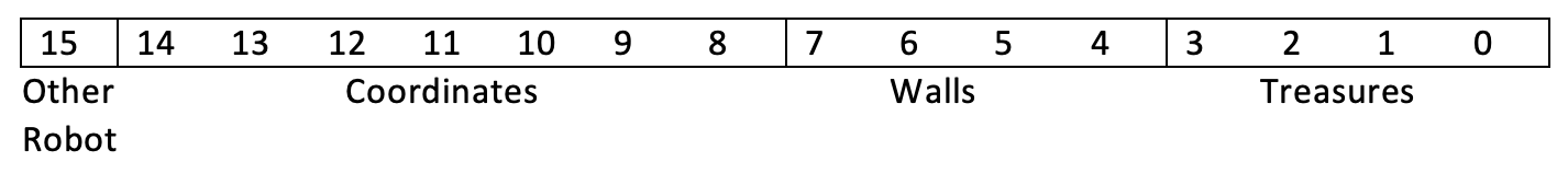
We were able to decide on an encoding for maze information and also decode those messages. We use 16 bits, the least four significant bits encode the color and shape of any treasure that is present. The next four bits each represent a wall in one of the four cardinal directions. The next seven bits encode the coordinates. To encode the coordinates, we use a single number. When that number is divided by n in (we assume the maze is size n-by-n), the remainder is the x-coordinate and the quotient is the y-coordinate. The final bit indicates whether or not another robot is detected.
We created byte encodings of a maze in an array and loop through it to simulate traversing it using right hand wall following. We use bit masks and switch statements to decode each message, and then write the corresponding message to the GUI.
In the 2 byte message packet sent from the transmitter to the receiver the data was formatted as such:
MSG[14] = {0,robot detected,0,0,0,0,0,0,0,0,0,0,0,0}
MSG[13:8] = {location}
MSG[7:4] = {north wall,east wall,south wall,west wall}
Robot traversing a 4x10 maze while updating the GUI on the day before competition:
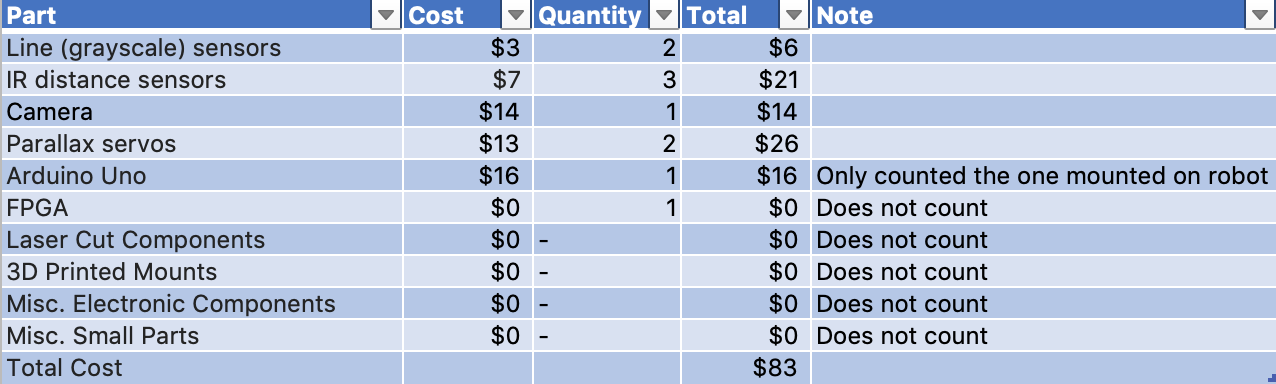
Robot Components and Cost
Final Performance
In the final competition, our robot performed far poorer than expected due to some unforeseen errors.
In the first round, our robot didn’t start at all. This was due to an issue that we’d had a few times the night before the competition, wherein the Arduino would crash during the setup function. This bug was previously fixed by uploading another Arduino program and then re-uploading the robot program. We were unable to complete this before the start of the first run so the robot never moved.
In the second round, our robot was able to go from one corner of the maze to the other. However, when our robot reached the opposite corner of the maze, it updated the GUI incorrectly and was incorrect about its location in the maze. This led to the robot believing it was cornered in a fully-explored, two-square box, and it stopped moving.
The GUI of our second round at the competition.
Future Improvements
In order to improve this robot in the future, the first thing that should be fixed is the interrupted setup problem. It is possible that this is a memory issue but since the program only uses 43% of program storage space and 69% of dynamic memory it is unlikely that this is the issue. To improve for the future, this bug could be explored further by switching the arduino on the robot with another arduino or with a genuine arduino. Based on these results, the origin of this bug could be traced back to see if this is a problem with our arduino, the fact that it is not a genuine arduino or if there is problem within the program.
In addition, in reality, the location was being encoded using 6 bits instead of 7 bits so it was unable to correctly transmit all 81 locations in the maze. Due to this, the actual location of the robot was truncated when it reached the opposite corner of the maze. This explains the problem with our GUI from our second run in the maze. We were unable to discover this bug earlier due to the fact that we never tested on a maze of this size. Thus we were oblivious to the fact that our location variable actually only encodes 64 unique locations and not 81.Our robot could be further improved by checking for other robots more frequently. Even though, we check for other robots at intersections, it is still possible to run into other robots while not at an intersection. Thus it is important to be continuously checking for other robots. In addition, when other robots are detected, our robot could avoid it by turning around. However, due to the fact that continuously performing the FFT function interferes with the servos, it is likely that another microcontroller would be needed. In addition, this would second microcontroller would give us the freedom to utilize more input and output pins on top of the added computational power. The drawback of this is from the fact that another battery would likely be needed to power a second Arduino.
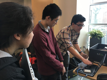
This is a picture of us when we realized all the things we could've improved on after the competition.
Conclusion
Although the individual components of our robot functioned fine normally (with the exception of shape detection), upon integrating we ran into far more issues than we expected. As a result, some of the projected functionalities for our robot in navigating the maze failed on competition day, while some other imagined functionalities -- treasure detection in particular -- did not have enough time to truly bloom. It is valuable to note that this was not a result of not attempting -- there simply was not enough time to figure out all the bugs that arose from having all these features running at once and we ended up having to prioritize.
We didn’t end up very high in the class standing, but we still were and are proud of the work that we have poured into our small son and the many accomplishments we have achieved, and all the things our son can do -- even if he can’t do them all at the same time. However, as a 15-week old in his first ever course, we’re proud that he’s managed to achieve so much.
Thank you to all the other students for working hard and frantically soldering together, to all the TAs for answering our many questions (and holding open lab at ungodly times), and to Kirstin for leading the class!