team8s
brandon, eric, henri, sophie
Milestone 1
Objectives:
- A robot that successfully follows a line
- A robot that successfully traverses a grid in a figure eight
Modifications to Robot
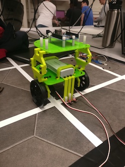
In order to implement line-following, it was necessary to add IR sensors -- we decided on adding 2, which would be arranged to be on either side of the line. (In some videos and pictures, we have three sensors -- we considered adding additional sensors to make the system more robust, but the middle one we temporarily added was/is not used.)
When adding the line sensors, we realized that we were going to have to take pieces off and on to change the battery, which was tedious and inefficient. As a result, we decided to add a second level to our robot, allowing us to move the battery. This will also allow us to incorporate more sensors in the future of our project.
Line Following
Note: Parameters adjusted so that robot follows a black line
We added 2 IR sensors to the robot that can sense a line. Using the serial monitor, we measured that the value used by the line sensors to detect white was 850, and the value for black was around 950. Depending on whether we were trying to follow a white or black line (with a dark or light background, respectively), we could switch the numbers in our code to accommodate the change.
When following a line, these two sensors hover just above the right and left edges of the line. Then, if the robot drifts left, the right sensor will be sensing the white line and vice versa if the robot drifts right. So if we find the right line sensor is seeing the white line, we speed up the left servo and slow down the right servo to compensate for the left drift until right sensor is no longer over the white line. If the left sensor is seeing the white line the same procedure is done except in the opposite direction.
We fine-tuned our line-following function in order to be more precise and tested it to follow a square.
We also discovered that our robot could first find a line and then follow it, as shown in this video.
          void loop() {

            //if L/R sensors sense white, correct until see black

          if (analogRead(SENSERIGHT) < 860) driftRight();

          else if (analogRead(SENSELEFT) < 860) driftLeft();

          else goStraight();

        }
Intersections
Although our robot was able to follow a line, it didn’t know what to do when encountering an intersection – the sensors would detect that they were both on a line and the robot had no protocols to deal with it. In order to manage this, we first attempted to ensure the robot would realize when it reached an intersection: when both sensors saw the line, the robot would stop using our fullStop() function. This took some trial and error, since the values we were using to detect the line and the surrounding material were a little off, and the robot would stop in the middle of the line because of a slight change in the color of the tiles under it, but fine-tuning the value fixed the issue.
After we confirmed that the robot could reliably detect an intersection, we created sharpLeft() and sharpRight() functions that we could deploy once the sensor reached an intersection. We first focused on just sharpLeft(), changing the output values to the servos and delay time in order to adjust the severity of the robot’s turn. After we figured out the appropriate values, we switched the servo values to create sharpRight() and tested it.
After this, we had the building blocks to create a figure eight!
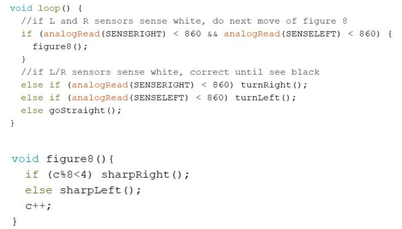
Figure Eight
To implement the figure 8, we hard coded in a sequence of four right turns, then four left turns. The sharp turns are executed in sequence whenever the robot encounters an intersection. To track the turns so far, we use a global counter, and we use the modulo operator to allow the robot to do continuous figure 8’s.