team8s
brandon, eric, henri, sophie
Lab 4: FPGA and Vision
FPGA team: Eric and Brandon
Arduino team: Henri and Sophie
FPGA
- read num of red or blue pixels
- whichever is most → either a red frame or a blue frame
- preventing overflow
In order to view the camera output, we must read the camera output and save it to a memory buffer. Then, the camera data is read from the memory buffer by the VGA driver.
With all of the appropriate memory and VGA driver modules set up for us already in the template, we only needed to focus on writing the camera data to the memory buffer correctly.
First we focused on writing simply writing to the memory buffer correctly by creating an English Flag:
To do this we focused on writing each pixel to the correct address in memory and setting the write enable to memory appropriately.
To read from camera:
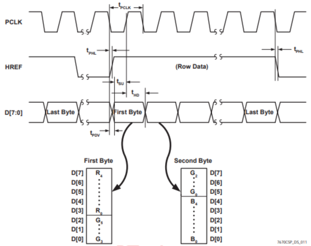
From this we can see that we should begin reading each pixel for a row when HREF goes high. Then, every other rising edge of PCLK signifies the beginning of the next pixel in the row. Since we want to store each pixel in memory in the RGB332 format, we take the MSBs for each color from the 2 bytes. The row is finished when HREF goes low.
The snippet shown below demonstrates how each pixel data is sampled from the 2 bytes and how the column address of each pixel is updated:
To update the row address, we can simply increment it each time HREF goes high since HREF signifies the beginning of a new row.
Frame Synchronization:
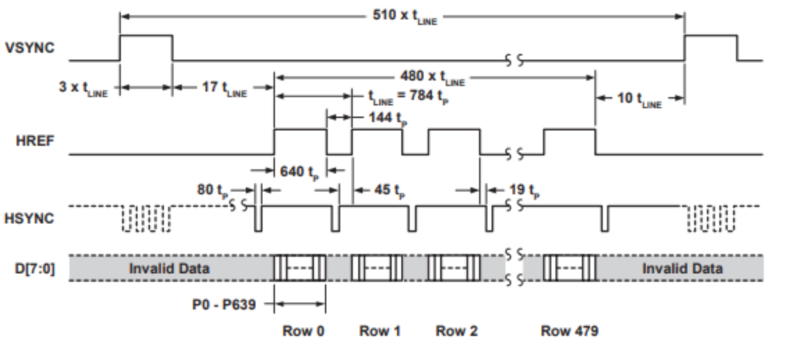
We use the VSYNC signal to detect the start of a new frame. As seen from the timing diagram above, each time VSYNC goes, high a new frame begins. Using this, we can reset our pixel address to start reading from row 0 column 0 on the rising edge of VSYNC.
Color Detection:
In order to tell if a shape our camera was looking at was red or blue, we continually checked the current pixel’s value on each posedge of the clock. If this was predominantly red, we would iterate RED_PIXELS; if it was predominantly blue, we would add to BLUE_PIXELS.
We also iterated a value “pixel_count” to determine if we were at the end of reading an entire frame.
Once we had finished reading an entire frame, we then checked if we had found significantly more red pixels than blue pixels; if so, then we iterated the variable RED_FRAMES; if there was significantly more blue than red, we iterated BLUE_FRAMES; and if the difference between red and blue pixels was relatively negligible, we iterated NONE_FRAMES. We then reset RED_PIXELS, BLUE_PIXELS, and pixel_count.
In order to prevent frame overflow, we ensured that if any of RED_FRAMES, BLUE_FRAMES, or NONE_FRAMES hit capacity (== 10’b1111111111), we decremented all the frames’ values by 1 (provided they were greater than zero).
We then chose output our result as follows:

That is, in bit 0 we would return a 0 if there were more blue frames and a 1 if there were more red frames; in bit 1, we would return a 1 if there were more “none” frames than either blue or red, and a 0 otherwise.
Shape Detection:
We attempted but were not able to implement shape detection. Our approach was to check for three important values: the first red/blue pixel on top, on the left, and at the bottom.
However, we realized after a lot of revamping of this code that we were unable to make our methods of shape detection work. This was partially because of faulty color detection as a result of imprecise camera output. The colors displayed by our camera were often not “pure” -- even the white walls, for example, had numerous red pixels that were throwing off our algorithm.
Because we realized that this was not working, and due to time constraints, we decided upon focusing on figuring out more precise color detection.
Color Bar Test
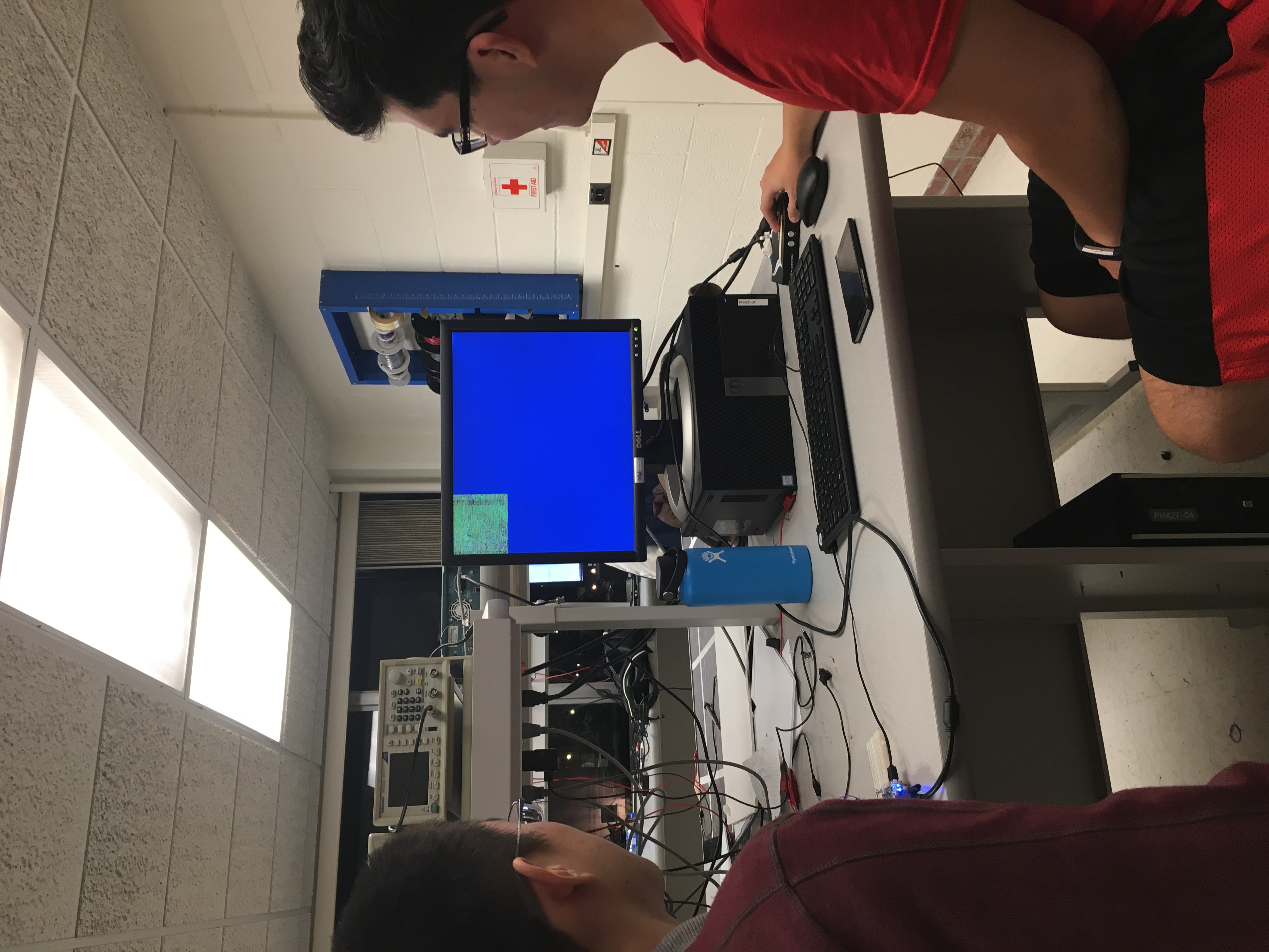
Working on Color Bar Test...not working yet
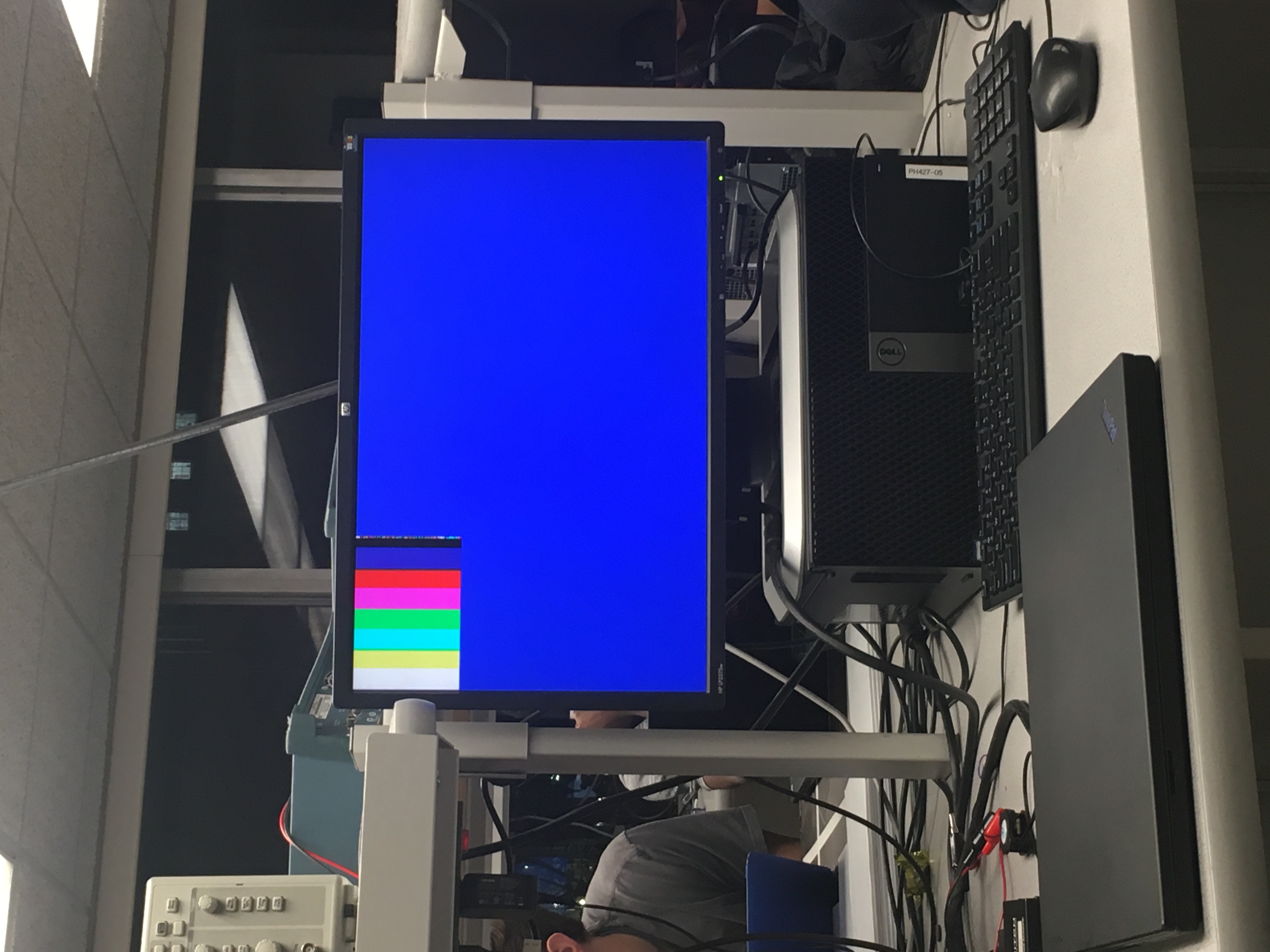
Color Bar Test Working!
Arduino Team
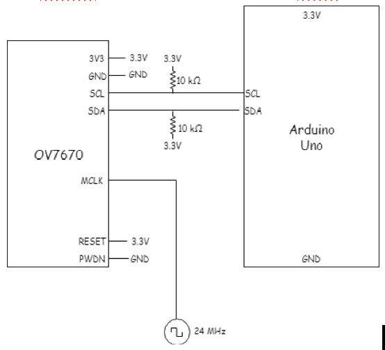
We set up the Arduino SDA and SDL pins to the camera as shown below:
We had to make sure to disable the internal pull-up resistors that are part of the Arduino’s I2C interface by commenting out these lines in the twi.c file:
//activate internal pullups for twi
digitalWrite(SDA,1);
digitalWrite(SCL,1);
We used the OV7670 camera datasheet http://web.mit.edu/6.111/www/f2016/tools/OV7670_2006.pdf to write registers to:
- Reset all registers: COM7
- Use the external clock as internal clock: CLKRC
- Set the camera to output the resolution and pixel format RGB 565, QCIF: COM7, COM15
- Enable a color bar test: COM7, COM17
- Vertical and mirror flip the output image: MVFP
- Fix the gain and other parameters (freeze AGC/AEC): COM9
- Enable scaling: COM3
The I2C address uses the least significant bit to distinguish between read and write and is 0x21.