team8s
brandon, eric, henri, sophie
Lab 1: Microcontroller
Subteams: Eric and Sophie, Brandon and Henri
Objective
- gain familiarity with Arduino
- begin creating an autonomous robot!
Materials
- Arduino Uno
- USB A/B cable
- Continuous rotation servos
- LED
- Potentiometer (100kΩ)
- Several resistors (330Ω)
- Solderless breadboard
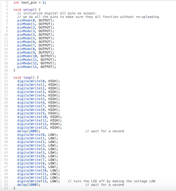
Blinking an Internal LED
We first downloaded the Arduino IDE and opened the “Blink” example code. File > Examples > 1.Basics > Blink. Click the checkmark and then the right-pointing arrow to upload the program to the Arduino.
Blinking an External LED
We modified the given code to blink an external LED with a resistor.
Analog Input/Output
The next part of the lab had us using the analog input pins of the Arduino to read values from a potentiometer. Because the Arduino reads voltage, and not resistance, we set up a voltage divider with the potentiometer another resistor. The code for this task was very simple, in the setup() function, we set the data transmission rate (in bits per second) for serial communication, using the line:
> Serial.begin(9600);
Then in the loop() function, we just read from the analog pin, print to the serial monitor, and wait, so we can actually read the values that get printed.
> Serial.println(analogRead(PINNAME)); > delay(500);
You can see (sort of) this functioning in the video below.
The next step to visualize the analog input was to map it to the output. The circuit for this is essentially the circuit for analog input, and the circuit for blink, combined together. Because the Arduino can only output digital signals, we simulate analog input by using pulse-width modulation (PWM). This means we alternate very quickly between high and low signals periodically. For a given duty cycle (a percentage), the signal is high for some portion of the period and low for the remainder. This is conveniently encapsulated into the built-in function analogWrite(), meaning that the code was again very simple. In setup(), we designate our PWM pin as output:
> pinMode(OUTPIN, OUTPUT);
Then in loop(), we just have to write the value that we read in:
> analogWrite(OUTPIN, analogRead(PINNAME));
The video below shows our code in action, as we turn the potentiometer, the brightness of the LED changes:
The final part of the lab involved mapping the analog input to a servo motor. Again, this is easy because Arduino has a built-in servo library. The most important thing to note is that the servos we were using were continuous rotation servos, meaning that the value written to the servo determines its speed and direction, not its position. Because we were getting strange results when we tried writing to the servo, we also added in code to print the values we were reading to help debug. We found that we could read values up to 1023 from the analog input, while the Servo.write() function expects values between 0 and 180. So, we normalized the value read to be in the 0-180 range. We then found that in most of that range, the servo moves at essentially its maximum speed. To get results that we could actually see, we again normalized the values to be in the range 80-100. This gave us much finer control, which you can see below:
Now that we’ve learned some basics about Arduino, it’s time to gather the parts and build a robot!
Through following pictures from previous years’ robots we screwed the mounts, servos and wheels to the body of the robot appropriately.
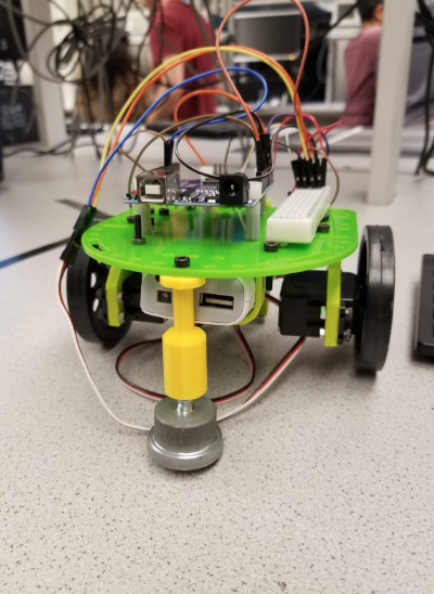
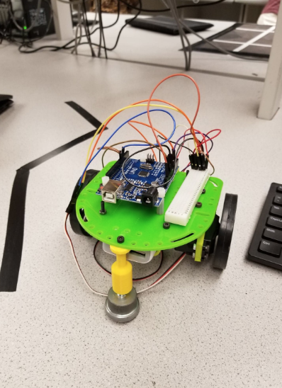
In order to have enough ports to power the two servos, a breadboard with an additional ground and power rail were added.
Autonomous Movement
Our next objective was to make our robot complete a task autonomously. We stuck with simple movement: moving forward, pausing, then moving backwards. This was achieved by setting the analog output of the servo pins to either 0, 90, or 180 to move forward, stop, or move backwards.
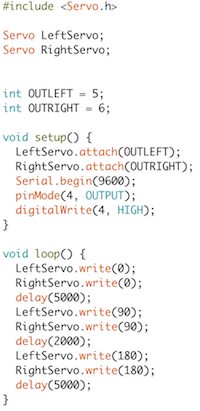
This allowed us to ensure that our robot's servos were correctly moving, as we initially discovered our servos were moving out of sync and the robot was deviating from its straight path. We were able to sync the servos and correct its path.
Its successful movement is documented here:
The movement depicted in this video starts halfway through the loop and ends at the halfway point again -- that is, it's first going backward, then forward, then stopping. Because the movement functions are in the loop, the robot will perform the movement over and over.